

Public content served from the new content model and resolved through migrated aliases.
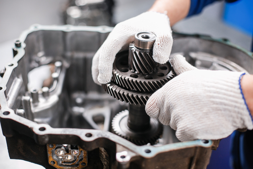
A gearbox is a kind of container for integrated and synchronized gear trains. In the operational sense, a gearbox is a machine component with the ability to change speed and torque between a driving device and a driven device, for example, between a motor and a coupled load. Gearboxes are also used to change the direction of rotation and the direction of the drive shaft. The mechanical components that enable these functions are called gears, and within gearbox terminology, there are different types.
Compared to other power transmission systems, such as pulley/belt, chain, or friction roller systems, gearboxes offer better speed control, greater transmission efficiency, high power, high working torque, and full speed range in low RPM applications. In general, they are compact, robust, and reliable machines. However, they are expensive and sophisticated equipment requiring specialized maintenance care associated with lubrication, mounting, tolerance adjustment, alignment, and condition monitoring.
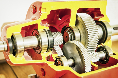
Depending on the need, different types of gears are available, among the most common are spur and helical gears, capable of transmitting power at various speeds and loads.
Also, bevel gears are specially designed to change the direction between the input and output shafts of the gearbox, for example, to convert the input of a horizontal axis to a vertical axis output.
Another type of gear system is the so-called endless screws, which can transverse changes in the direction of the input and output axes. The arrangement and design of the gears, give great versatility to these machines, allowing compact, robust and reliable designs, an example of this is the arrangements of gearboxes with various stages of transmission and planetary type designs.
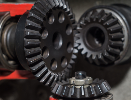
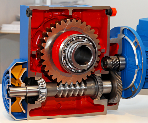
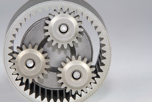
Gearboxes could be broadly classified into reducers and multipliers, depending on their function of decreasing or increasing the speed of rotation of input versus output. A gearbox that increases the input speed is called a multiplier; the opposite is a reducer gearbox.
Besides, gearboxes can be divided into single-stage transmission systems, those that only have one gear train, or multi-stage gearboxes, those formed by two or more gear trains, with intermediate speed and torque changes before reaching the output. In many applications, gearboxes are used as an intermediate machine for converting speed and torque between a driver and a driven machine; for example, a reduction gearbox between a steam turbine and a generator.
Some machines are intrinsically a gearbox with operational functions, such as integrated equipment like gear pumps or multi-stage centrifugal compressors whose impellers are installed directly on the shafts of gearboxes.
The design and manufacture of gears are specialized activities of very high precision. There is an extensive number of concepts associated with the design, geometry and construction of these machine elements. The AGMA standards are responsible for standardizing them, if you need to delve into this topic, recommends reviewing the specialized literature. For the specific case of vibration analysis and condition monitoring, the following concepts are those of daily use:

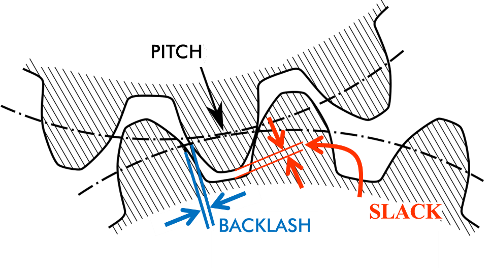
The AGMA (American Gear Manufacturers Association) standards establish standardized guidelines for the design and manufacture of gears and gearboxes. The API 613 standard covers aspects related to gearboxes for the oil and gas industry. The ISO 10816-21 establishes some acceptance limits based on frequency bands.
All of these standards suggest some values for speed amplitude and acceleration. However, they are very general reference values that should be adjusted to each gearbox's operational and functional conditions. To deepen these recommendations, it is suggested to consult these standards.
Proper gearbox monitoring can be achieved using the performance baseline as a benchmark, much of the gearbox failure analysis is based on detecting pattern changes, rather than monitoring variables against absolute levels.
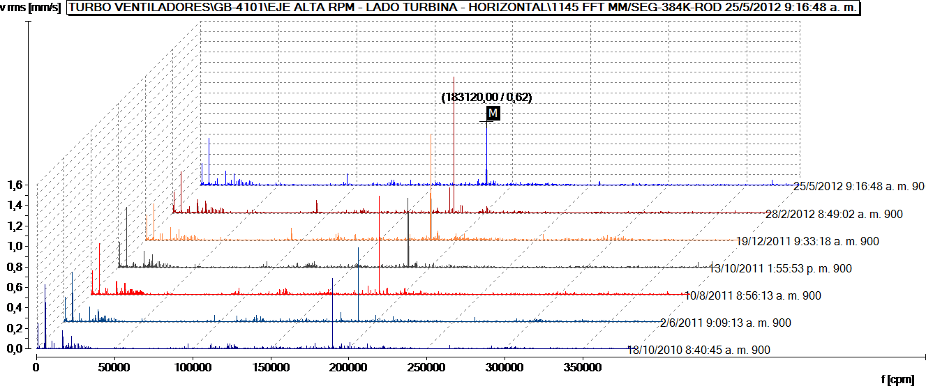
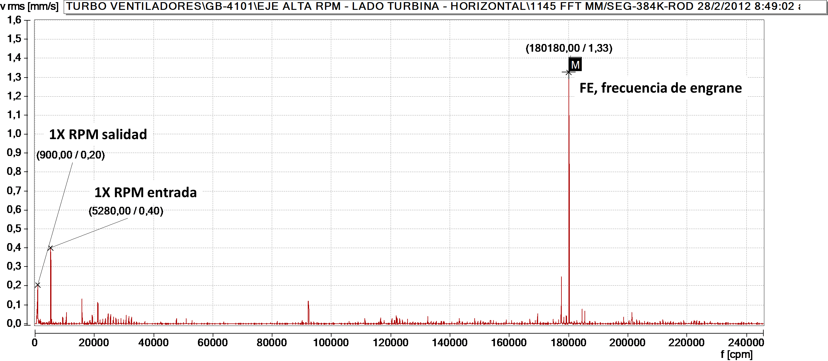
These machines produce complex vibration signals in which inherent operating frequencies, random noise, and other failure frequencies can be combined, both "standard" and specific failures associated with gear failure modes. We can classify the vibration frequencies in a gearbox as:


|
FAILURE MODE |
SYMPOTMS |
CAUSES |
RECOMMENDATIONS |
| MISALIGNMENT | Amplitude increase in the axial direction of the axes. Appearance of 2X, 3X RPM, and 2X, 3X FE harmonics. | Wrong alignment procedures, loss of tolerances, thermal expansion. | Align based on precision procedures and standards. |
| EXCESSIVE WEAR | Increased amplitude of the 1XGMF and 1X sidebands. Appearance of gear's natural frequency. | Improper lubrication, contaminated or degraded lubricant. Change of wear pattern. Assembly and adjustment failures. | Do oil analysis, investigate and eliminate sources of contamination. Clean the lubrication system. Review adjustment and tolerance procedures. |
| EXCESSIVE BACKLASH | Increased amplitude of the 1XGMF and 1X sidebands. Appearance of gear's natural frequency. | Bad assembly, design or manufacturing flaws, wear. | Oil analysis. Review assembly procedures and tolerances. |
| OVERLOAD | Increased amplitude of 1XGMF, multiple 1X RPM sidebands. | Operation outside of design conditions. | Evaluate operational conditions. |
| HIGH FRICTION | Increase of the 1XGMF component, rise of the global amplitude in acceleration, and shock pulse. | Lubrication failures and/or lubricant quality. Component assembly and tolerances. | Do oil analysis, check and reduce sources of contamination. Clean the lubrication system. |
| BROKEN TEETH | Synchronous impact pattern in the time waveform with 1X of damaged gear. | Overload, fatigue, adjustments and tolerances. | Evaluate operational conditions, material analysis. |
| ASSEMBLY OR MANUFACTURING FAILURES | Increased amplitude of the 1XGMF and 1X sidebands. Appearance of Hunting Tooth Frequency (HFT) or the Gear Assembly Phase Frequency (GAPF). | Manufacturing defects in geometry and/or materials. Irregular teeth surface. Changes from the original wear pattern. | Improve quality control system and maintenance procedures. |
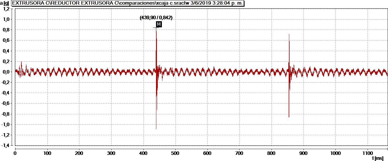
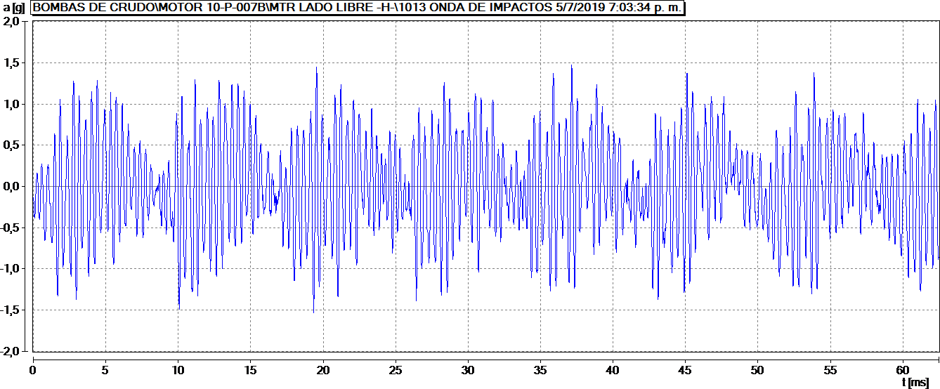
The analysis of failures in gearboxes often involves the study of various variables and multiple symptoms. Therefore it is always necessary to design comprehensive condition monitoring programs that include vibration analysis, acceleration envelope analysis, airborne ultrasonic analysis, tribology or physical-chemical analysis of lubricants and infrared thermography, all these predictive technologies aimed at determining the symptoms of wear and friction, common elements in most failure modes of industrial gearboxes.