

Public content served from the new content model and resolved through migrated aliases.
In industrial maintenance, one of the most critical yet overlooked questions is defining an industrial asset. This definition directly impacts how organizations plan maintenance, monitor equipment, manage reliability programs, and even how PdM software licenses are calculated.
The international standard ISO 14224 provides a well-structured taxonomy for industrial equipment and reliability data collection. At its core, the standard organizes assets into hierarchical levels, culminating at level 6: the equipment unit. Power-MI adopts this level as the practical definition of an industrial asset. By focusing on level 6, we align our platform with global best practices, ensuring that reporting, monitoring, and management are consistent and comparable across plants, industries, and geographies.
Why is this delimitation essential? Because predictive maintenance is built on clarity. If engineers, reliability managers, and software tools operate with inconsistent definitions of what an asset is, confusion spreads into inspection reports, KPIs, and investment decisions. Conversely, when assets are defined objectively and consistently, data integrity improves, reliability analysis becomes meaningful, and licensing remains transparent and fair. This White Paper addresses precisely that challenge: providing a practical guide to defining industrial assets within the ISO 14224 framework.
Defining equipment consistently is essential for predictive maintenance and reliability management. ISO 14224 provides a clear taxonomy that organizes the industrial environment into hierarchical levels, from the industry as a whole down to individual parts. Within this structure, Power-MI aligns with Level 6: Equipment Unit as the practical definition of equipment.
In the hierarchy, the upper levels (Company, Plant, Section) establish organizational and physical context, while lower levels (Subunit, Component, Part) describe subdivisions within equipment. The equipment unit (Level 6) is the pivot point: it represents the physical item to which condition monitoring and predictive maintenance activities are applied, and the level at which inspection reports are generated.
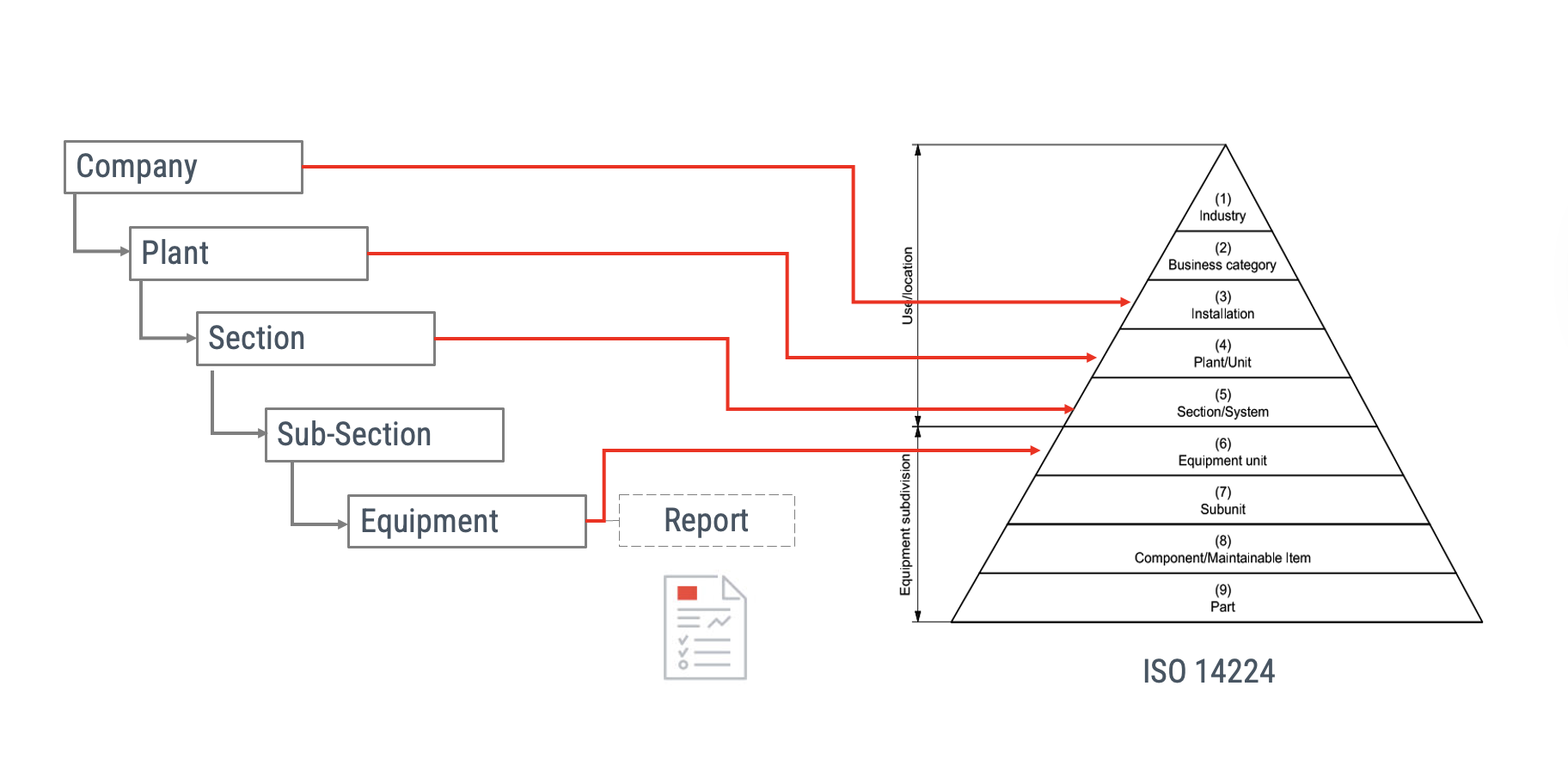
The diagram above illustrates how Power-MI translates ISO 14224 taxonomy into a practical hierarchy:
In Power-MI, we added the Sub-Section level because many clients require an extra layer to locate and organize equipment. This additional level provides flexibility for complex plants where sections alone are not sufficient. In the following sections, we will explore practical cases where this subdivision becomes essential.
This mapping highlights how organizational structure connects to technical structure. For example:
PdM perspective — the report defines the boundary. In predictive maintenance and condition monitoring, equipment is the object to which the inspection or monitoring report is issued. In practice, the report boundary sets the equipment boundary. For a motor–pump set (an electric motor coupled to a centrifugal pump), the common question is whether the motor and the pump are two pieces of equipment or one. The decisive test is: when you perform vibration, thermography, or visual inspections, do you issue one report for the motor and another for the pump, or a single report for the motor–pump set? In most plants, a single report is produced; therefore, the equipment is the motor–pump set—not the components separately.
By adopting Level 6 as “equipment,” Power-MI ensures that users define and manage units consistently, avoiding confusion between higher-level groupings and lower-level components. This clarity supports data integrity, reliability analysis, and transparent software licensing.
Clear delimitation of equipment is critical to ensure consistent reporting, accurate condition monitoring, and transparent software licensing. While ISO 14224 provides a structured hierarchy, in practice each organization must decide where to draw the boundary between one equipment unit and another. The following principles provide practical guidance:
One of the most common questions in predictive maintenance is how to define a motor–pump assembly: should the motor and the pump be considered two separate pieces of equipment, or one? This example illustrates how reporting practices guide the definition of equipment in Power-MI.
From a predictive maintenance perspective, equipment is the entity for which a condition monitoring or inspection report is issued. The report boundary defines the equipment boundary. In other words, the practical test is simple: when you conduct vibration analysis, thermography, or visual inspections on a motor–pump set, do you prepare one report for the motor and another for the pump, or do you produce a single report for the motor–pump assembly?
In most plants, maintenance engineers prepare a single report covering the motor and pump together, since they are mechanically coupled and function as one operating unit. In such cases, the equipment is defined as the motor–pump assembly, not as two separate items. This aligns with ISO 14224 at Level 6 (equipment unit), where the monitored object of reliability data and maintenance reporting is established.
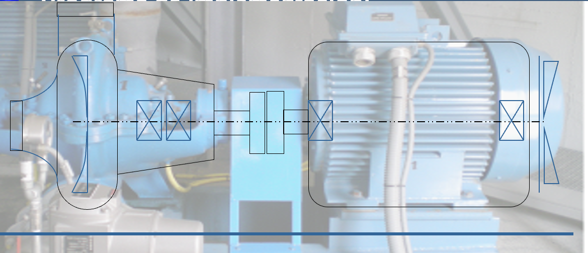
This approach emphasizes clarity and consistency: equipment is defined not only by its physical boundaries, but also by how it is monitored, reported, and managed. For Power-MI users, adopting the “report-driven definition” ensures alignment with real maintenance practices and avoids artificial inflation of equipment counts.
Conveyors illustrate the challenge of defining equipment when multiple elements form part of a single operational line. A conveyor may include motors, gearboxes, pulleys, and rollers, often duplicated along its length. Each of these components can have distinct vibration measurement points, raising questions about whether they should be classified as individual pieces of equipment or as a single unit.
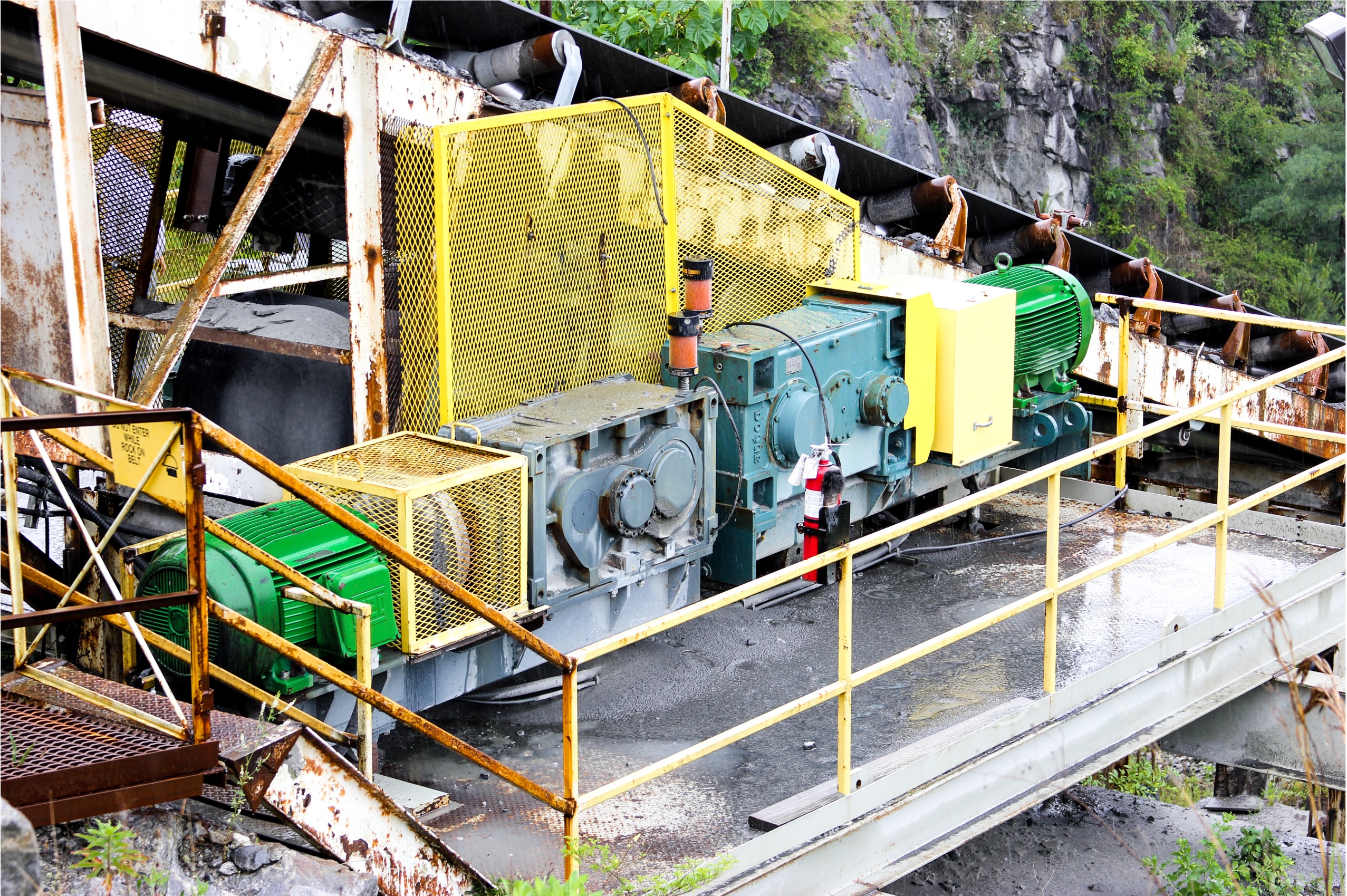
In Power-MI, the guiding principle remains: define equipment according to reporting practice. If the maintenance team issues a single condition monitoring report for the entire conveyor line, then the conveyor is considered one equipment unit. However, if separate reports are produced for each drive motor, gearbox, or pulley, then each monitored element can be defined as independent equipment.
This approach allows flexibility without losing consistency. Power-MI’s Sub-Section level can be used to organize large systems like conveyors into logical groups, while still keeping a clear definition of what constitutes equipment for reporting and licensing purposes. By mapping reports directly to equipment, reliability engineers can manage complex machinery without ambiguity and ensure comparability across different plants and sections.
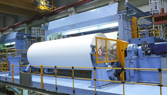
A winder is a large and complex piece of machinery used to process and wind paper into rolls. Its main visible components are the roller, the motor and gearbox, and the supporting bearings. The common question is whether the motor and roller should be considered separate equipment. In practice, since vibration, thermography, and bearing monitoring are usually reported as one, the winder is treated as a single equipment unit that includes the roller, bearings, transmission system, motor, and gearbox.
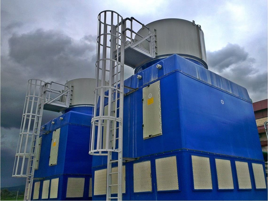
Cooling towers often raise the question of whether the tower should be considered one equipment unit or a subsystem with its internal components (fan, motor, gearbox, water pumps). In Power-MI, the prevailing practice is to define the cooling tower as a subsystem, and then treat each of its critical rotating elements—such as the fan motor or gear drive—as separate equipment. This approach supports precise condition monitoring, as these rotating components are monitored and reported independently, while the tower structure itself remains part of the subsystem.
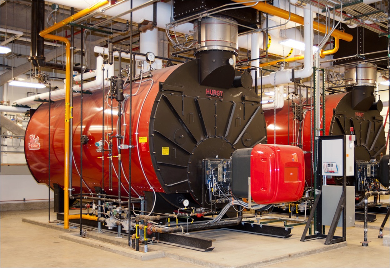
For boilers, confusion sometimes arises over whether to treat the boiler as one equipment unit or as a subsystem with its own components (burners, pumps, heat exchangers, valves). The standard practice is to define the boiler itself as an equipment unit. Although its components are monitored with different techniques (temperature, pressure, vibration, ultrasonic thickness), they all contribute to the operational reliability of the boiler as a single entity. By considering the boiler as equipment, reliability engineers maintain clarity in reporting and avoid unnecessary subdivision.
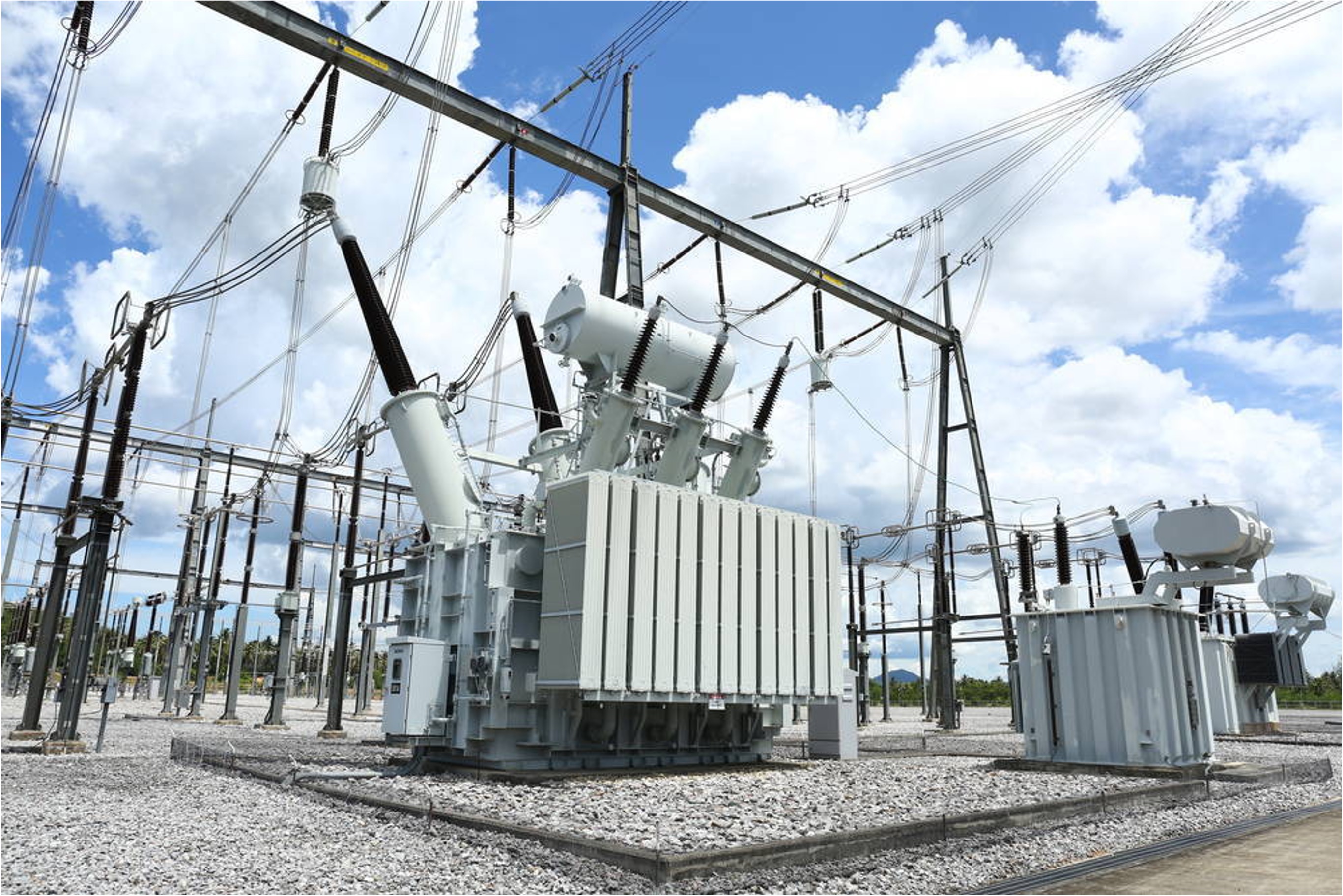
Substations are often recorded as a single equipment item, but they consist of multiple critical assets such as transformers, oil tanks, heat exchangers, and pumps. The practical guideline is to register the substation as a subsystem and define each transformer or critical rotating element as separate equipment, especially when independent reports are generated for them.
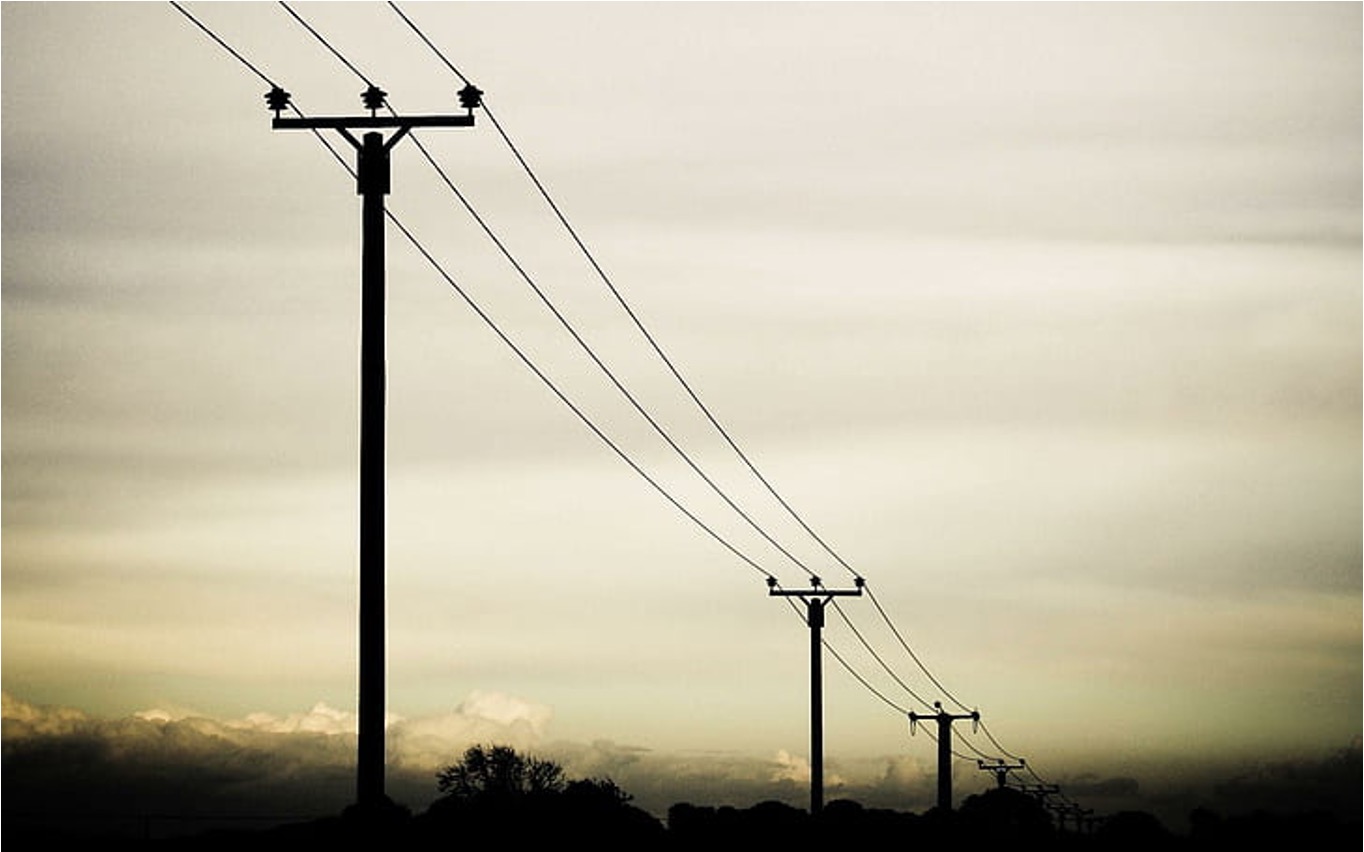
Transmission lines present a unique challenge. If defined as a single equipment unit covering long distances, reporting becomes imprecise—failures could be anywhere along the line, including multiple towers, insulators, or conductors. The best practice is to divide lines into manageable segments, either by kilometers or by operational regions. This ensures that reports specify failure locations clearly, while avoiding excessive fragmentation into very short segments.
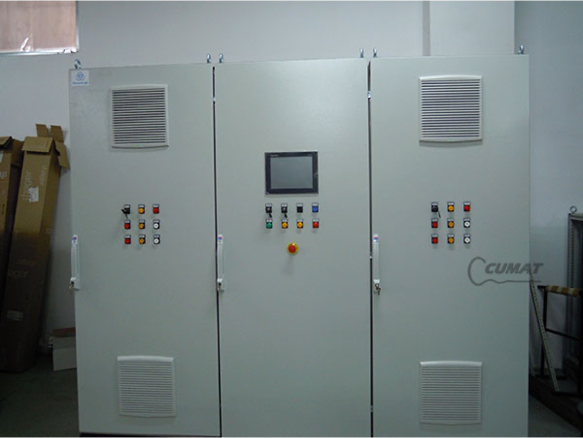
Confusion with switchboards arises when they contain multiple circuits or assemblies. The guiding criterion is whether a circuit is functionally tied to a specific mechanical or electrical equipment item. In most cases, the best practice is to treat the switchboard as a standalone equipment unit. When multiple switchboards are grouped physically but serve different functions, they should be divided according to their physical and functional boundaries, ensuring clarity in monitoring and reporting.
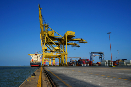
A ship-to-shore (STS) crane is a large and complex structure typically found in port terminals. It should be defined as a system or subsystem, since it contains multiple equipment items that are monitored and reported independently. Within an STS crane, common equipment units include the hoisting motor and gearbox, trolley drive motors, boom hoist, slewing mechanism, hydraulic pumps, and electrical switchgear. Each of these items can be treated as distinct equipment in Power-MI, while the crane as a whole is best considered a subsystem to maintain clarity.
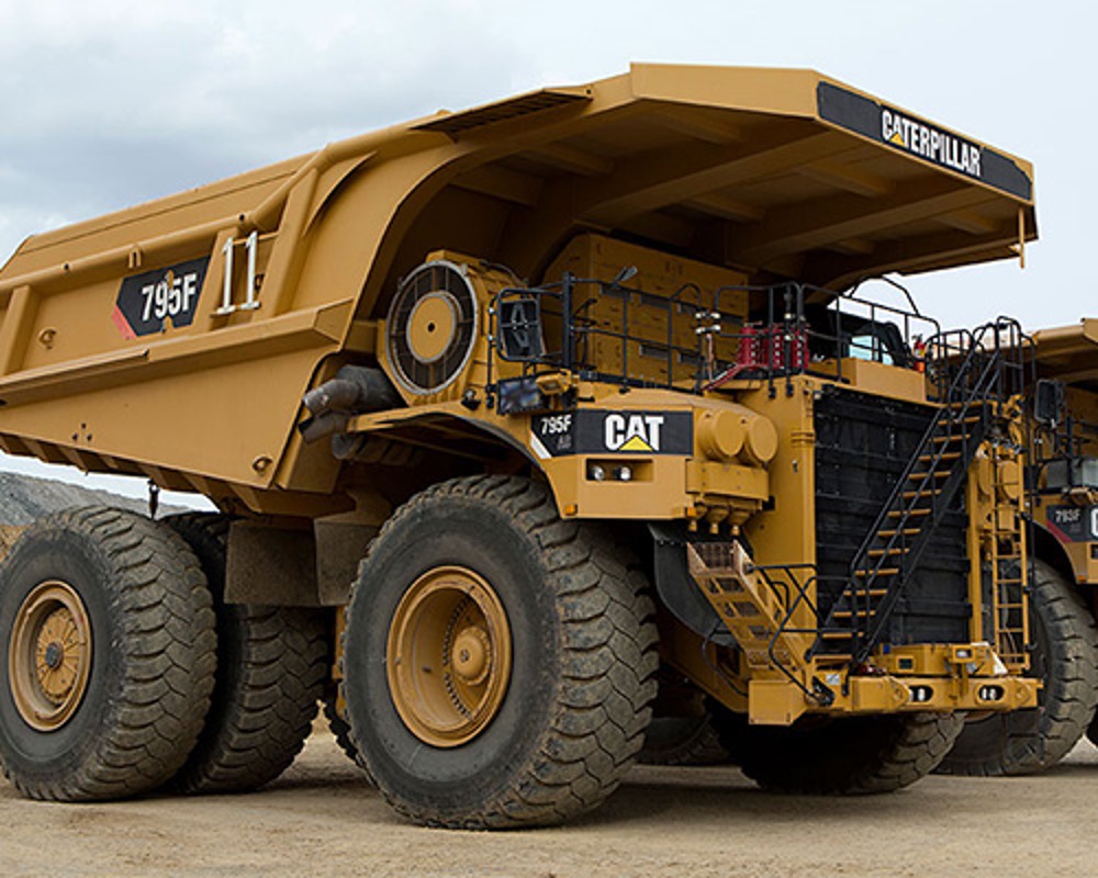
Similar to cranes, dump trucks combine multiple critical components that can be monitored separately. While the dump truck as a whole can be seen as a subsystem, its individual equipment units include the diesel engine, transmission system, hydraulic lifting system, cooling system, alternator, and wheel motors (in electric-drive trucks). Reliability engineers often issue separate reports for these subsystems, particularly the engine and hydraulics. This makes the dump truck best treated as a subsystem grouping, with condition monitoring tied to its individual equipment.
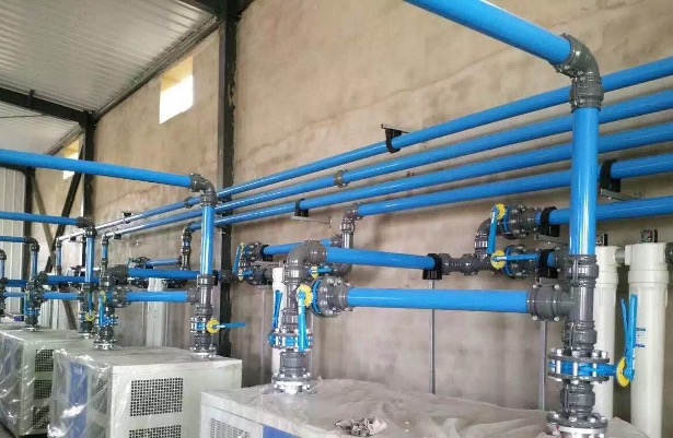
Piping networks are among the most challenging cases for equipment delimitation. For long, linear stretches—such as water pipelines or oil transportation lines—the recommended practice is to divide them into segments, similar to electrical transmission lines. This segmentation ensures that monitoring reports can pinpoint failure locations without including excessively long distances under a single equipment entry. Inside industrial plants, however, pipes often converge and interconnect. In such cases, they are better defined by plant area or sector. Another important decision is whether to include accessories such as valves, flow meters, and regulators within the same equipment boundary. The choice depends on their criticality: if an accessory significantly affects the process or requires separate condition monitoring, it should be registered as standalone equipment. Otherwise, it can remain part of the piping system definition.
Defining equipment consistently is rarely straightforward. Engineers and reliability professionals often face complex situations where the boundary between one equipment unit and another is blurred. Some of the most common challenges include:
Overall, the greatest challenge is balancing precision with practicality. Without clear and consistent delimitation rules, predictive maintenance programs risk confusion, unreliable data, and inefficient use of software resources.
To overcome the challenges of equipment delimitation, organizations should adopt clear, practical, and standardized approaches. The following best practices provide a roadmap:
By following these practices, companies can align equipment definitions with reporting realities, reduce confusion, and maximize the value of predictive maintenance programs.
Defining equipment is not an abstract exercise—it is the foundation for reliability engineering, predictive maintenance, and effective use of Power-MI. Clear definitions ensure that reports are accurate, monitoring is consistent, and reliability data is meaningful. They also guarantee transparency in software licensing, allowing companies to scale their predictive maintenance initiatives fairly and sustainably.
In predictive maintenance, clarity is power. By adopting consistent equipment delimitation, organizations enable accurate monitoring, trustworthy data, and confident decision-making. For Power-MI users, this discipline ensures that every report aligns with global standards and that every license reflects true operational needs. In short, precise definitions of equipment are the key to reliable operations and fair, scalable digital transformation in maintenance.